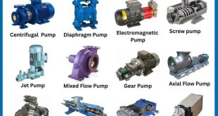
Classification of Centrifugal Pump
Centrifugal pumps are classified in several ways. Pumps may be classified:
• in terms of energy conversions (volute type and diffuser vane ring type);
• in terms of fluid flow through the pump (radial, mixed flow and axial flow);
• as either single stage or multistage i.e. in terms of number of stages;
• according to the design of the casing;
• according to the design of the impeller; and
• in terms of their application.
Centrifugal Pump Classification by Flow
Centrifugal pumps can be classified based on the manner in which fluid flows through the pump. The manner in which fluid flows through the pump is determined by the design of the pump casing and the impeller. The three types of flow through a centrifugal pump are radial flow, axial flow, and mixed flow.
Radial Flow Pumps
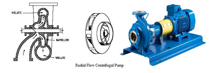
In a radial flow pump, the liquid enters at the center of the impeller and is directed out along the impeller blades in a direction at right angles to the pump shaft. The impeller of a typical radial flow pump and the flow through a radial flow pump are shown.
Axial Flow Pumps
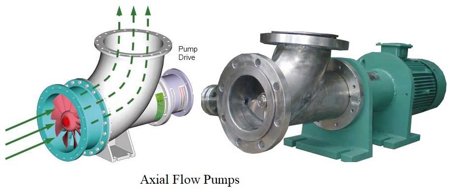
In an axial flow pump, the impeller pushes the liquid in a direction parallel to the pump shaft. Axial flow pumps are sometimes called propeller pumps because they operate essentially the same as the propeller of a boat. The impeller of a typical axial flow pump and the flow through a radial flow pump are shown.
Mixed Flow Pumps
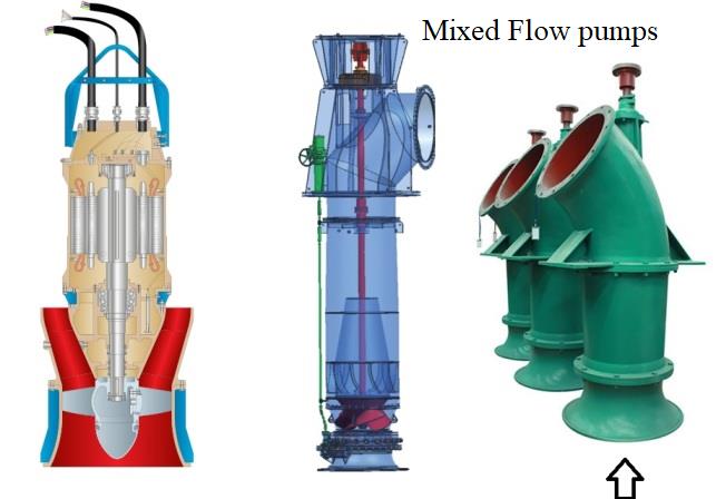
Mixed flow pumps borrow characteristics from both radial flow and axial flow pumps. As liquid flows through the impeller of a mixed flow pump, the impeller blades push the liquid out away from the pump shaft and to the pump suction at an angle greater than 90 degree. The impeller of a typical mixed flow pump and the flow through a mixed flow pump are shown.
Centrifugal Pump Classification by Number of stages
A centrifugal pump with a single impeller that can develop a differential pressure of more than 150 psid between the suction and the discharge is difficult and costly to design and construct.
A more economical approach to developing high pressures with a single centrifugal pump is to include multiple impellers on a common shaft within the same pump casing. Internal channels in the pump casing route the discharge of one impeller to the suction of another impeller. Picture shows a diagram of the arrangement of the impellers of a five-stage horizontal pump and ten stage vertical multistage pump. The water enters the pump from the top left and passes through each of the four impellers in series, going from left to right. The water goes from the volute surrounding the discharge of one impeller to the suction of the next impeller.
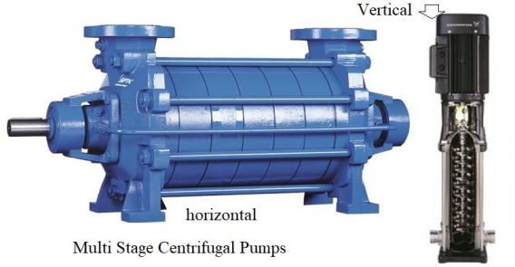
A pump stage is defined as that portion of a centrifugal pump consisting of one impeller and its associated components. Most centrifugal pumps are single stage pumps, containing only one impeller. A pump containing seven impellers within a single casing would be referred to as a seven-stage pump or, generally, as a multi-stage pump.
Centrifugal Pump Classification According to the Design of Casing
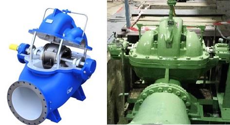
Centrifugal pumps are also classified in terms of the design of the casing. Both axially and radially split single casings are used for centrifugal pumps. Axially and radially split single casing are illustrated in Figures 8 and 9 respectively. The discharge connections are usually located in the lower half thereby enabling the upper half to be lifted and the rotor laid bare for inspection or removal without disconnecting the pump, either from its foundation or from the suction and discharge piping. The disadvantage of this type is the difficulty in maintaining a seal at the joint when at higher pressures. As the working pressure increases, radially split casings are preferred because of the inherent strength in their construction.
Centrifugal Pump Classification According to the Design of Impeller
Impellers of pumps are classified based on the number of points that the liquid can enter the impeller and also on the amount of webbing between the impeller blades. Impellers can be either single suction or double-suction. A single-suction impeller allows liquid to enter the center of the blades from only one direction. A double-suction impeller allows liquid to enter the center of the impeller blades from both sides simultaneously. The figure shows simplified diagrams of single and double-suction impellers.
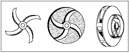
Impellers can be open, semi-open, or enclosed. The open impeller consists only of blades attached to a hub. The semi-open impeller is constructed with a circular plate (the web) attached to one side of the blades. The enclosed impeller has circular plates attached to both sides of the blades. Enclosed impellers are also referred to as shrouded impellers. the picture shows examples of open, semi-open, and enclosed impellers.
The impeller sometimes contains balancing holes that connect the space around the hub to the suction side of the impeller. The balancing holes have a total cross-sectional area that is considerably greater than the cross-sectional area of the annular space between the wearing ring and the hub. The result is suction pressure on both sides of the impeller hub, which maintains a hydraulic balance of axial thrust.
Read Download Free Pump Books>>
Centrifugal Pump Classification in terms of use or Application
One of the more important methods of classifying these pumps is in terms of their application like Pump used to feed water into a boiler is called Boiler Feed Water Pump. The intended application is a major factor in impeller and casing design, materials used and other mechanical and hydraulic features.
[bws_pdfprint] Boilersinfo Boiler and Mechanical Power Digital Library
