 Boilersinfo Boiler and Mechanical Power Digital Library
A valve is a mechanical device that controls the flow of fluid and pressure within a system or pipe. A valve controls the system or processes fluid flow and pressure by stopping, starting, and Regulating it.
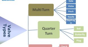
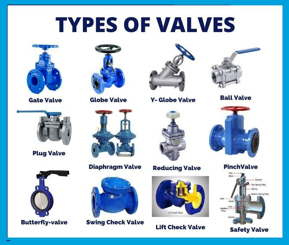
Types of valves and their Classification
Although all valves have the same basic components and function to control flow in some fashion, the method of controlling the flow can vary dramatically. There are many Different Types of valves used in the industry like
- Gate Valve
- Globe Valve
- Y – Type Globe Valve
- Ball Valve
- Plug Valve
- Diaphragm Valves
- Reducing Valves
- Pinch Valve
- Butterfly Valve
- Needle Valve
- Check Valve
- Relief & safety valve
- Solenoid Valve

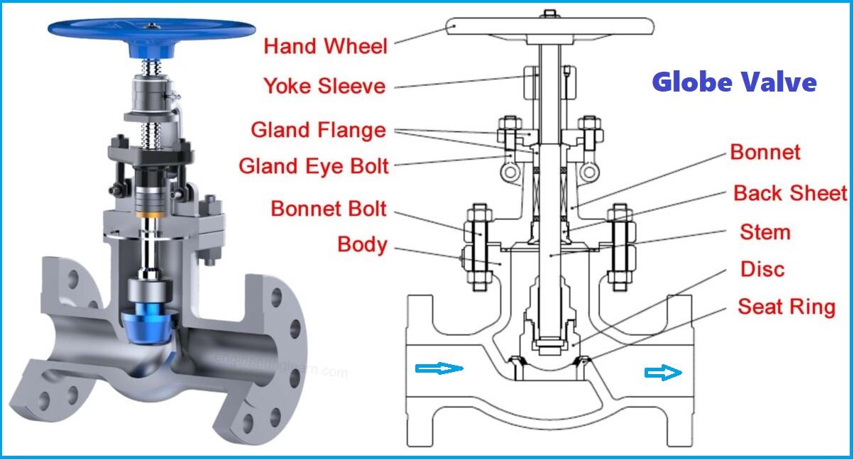
Globe Valves
A globe valve is a linear motion valve used to stop, start, and regulate fluid flow. The essential principle of globe valve operation is the vertical movement of the disk away from the seat. This causes the annular space between the disk and seat ring to close as the valve is closed gradually. This characteristic gives the globe valve good throttling ability, Which permits its use in regulating flow. Therefore, the globe valve may be used to stop and start the fluid flow and control flow. When compared to a gate valve, a globe valve generally yields much less seat leakage. This is because the disk-to-seat ring contact is more at right angles, which permits the force of closing to seat the disk tightly.
Y-Body Design globe valve
The Figure illustrates a typical Y-body globe valve. This design is a remedy for the high-pressure drop inherent in globe valves. The seat and stem are angled at approximately 45°. The angle yields a straighter flow path (at the whole opening) and provides the stem, bonnet, and packing a relative pressure-resistant envelope. Y-body globe valves are best suited for high pressure and other severe services.
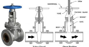
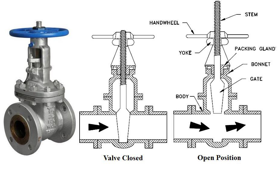
Gate Valve
A gate valve is a linear motion valve used to start or stop the fluid flow; however, it does not regulate or throttle flow. The name gate is derived from the appearance of the disk in the flow stream. The disk of a gate valve is completely removed from the flow stream when the valve is fully open. Hence, there is little pressure drop across an open gate valve. When the valve is fully closed, a disk-to-seal ring contact surface exists for 360°, and good sealing is provided. A gate valve can be used for various fluids and provides a tight seal when closed.
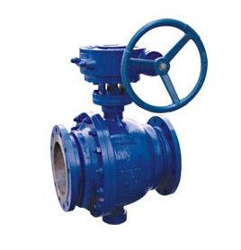
Ball valve
A ball valve is a rotational motion valve that uses a ball-shaped disk to stop or start fluid flow. The ball, shown in Figure, performs the same function as the disk in the globe valve.
When the valve handle is turned to open the valve, the ball rotates to a point where the hole through the ball is in line with the valve body inlet and outlet. When the valve is shut, the ball is rotated so that the gap is perpendicular to the flow openings of the valve body, and the flow is stopped.
Most ball valve actuators are of the quick-acting type, which requires a 90° turn of the valve handle to operate the valve. Other ball valve actuators are planetary gear-operated. This type of gearing allows a relatively small operating force to operate a fairly large valve.
Advantages: A ball valve is generally the least expensive of any valve configuration and has low maintenance costs. In addition to quick, quarter turn on-off operation, ball valves are compact, require no lubrication, and give tight sealing with low torque.
Plug valve
A plug valve is a rotational motion valve used to stop or start fluid flow. The name is derived from the shape of the disk, which resembles a plug. The simplest form of a plug valve is the petcock. The body of a plug valve is machined to receive the tapered or cylindrical plug. The disk is a solid plug with a bored passage at a right angle to the longitudinal axis of the pin.
In the open position, the passage in the plug lines up with the inlet and outlet ports of the valve Figure plug Valve body. When the plug is turned 90° from the open position, the solid part of the plug blocks the ports and stops the fluid flow. Plug valves are available in either a lubricated or no lubricated design and with various port openings through the plug and several plug designs.
Also, Read
Pump, types of pumps, and centrifugal pump working principle
Diaphragm Valves
A diaphragm valve is a linear motion valve used to start, regulate, and stop fluid flow. The name is derived from its flexible disk, which mates with a seat located in the open area at the top of the valve body to form a seal. A diaphragm valve is illustrated in Figure.
Diaphragm valves are, in effect, simple “pinch clamp” valves. A resilient, flexible diaphragm is connected to a compressor by a stud molded into the diaphragm. The compressor is moved up and down by the valve stem. Hence, the diaphragm lifts when the compressor is raised. As the compressor is lowered, the diaphragm is pressed against the contoured bottom in the straight-through valve illustrated in Figure 14 or the body weir in the weir-type valve shown in Figure.
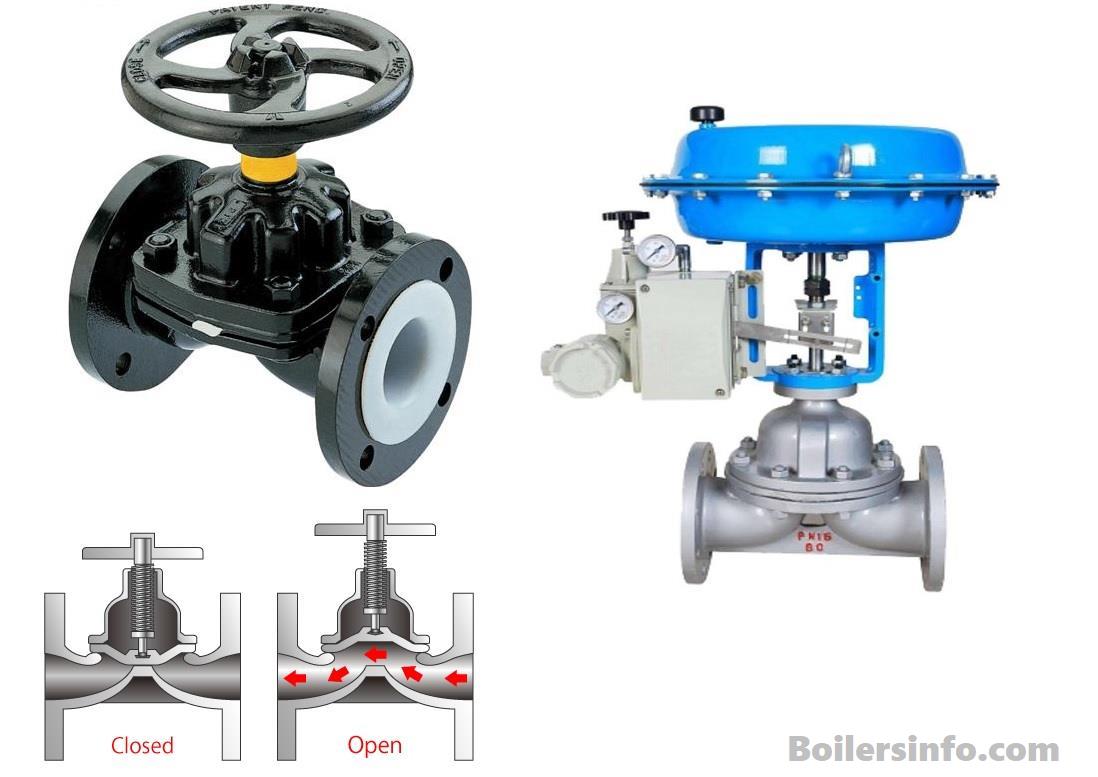
Diaphragm valves are particularly suited for handling corrosive fluids, fibrous slurries, radioactive fluids, or other fluids that must remain free from contamination.
Reducing Valves
Reducing valves automatically reduce supply pressure to a preselected pressure as long as the supply pressure is at least as high as the selected pressure. Illustrated in Figure.
The main valve’s principal parts are the main valve, an upward-seating valve that has a piston on top of its valve stem, an upward-seating auxiliary (or controlling) valve, a controlling diaphragm, and an adjusting spring and screw.
Working principle of Reducing valve :
Reducing valve operation is controlled by high pressure at the valve inlet and the adjusting screw on top of the valve assembly. The pressure entering the main valve assists the main valve spring to keep the reducing valve closed by pushing upward on the primary valve disk. However, some of the high pressure is bled to an auxiliary valve on top of the main valve. The auxiliary valve controls the admission of high pressure to the piston on top of the main valve. The piston has a larger surface area than the central valve disk, resulting in a net downward force to open the main valve. The auxiliary valve is controlled by a controlling diaphragm located directly over the auxiliary valve.
The controlling diaphragm transmits a downward force that tends to open the auxiliary valve. The downward force is exerted by the adjusting spring, which is controlled by the adjusting screw. Reduced pressure from the main valve outlet is bled back to a chamber beneath the diaphragm to counteract the downward force of the adjusting spring. The position of the auxiliary valve, and ultimately the position of the main valve, is determined by the position of the diaphragm. The position of the diaphragm is determined by the strength of the opposing forces of the downward force of the adjusting spring versus the upward force of the outlet reduced pressure. Other reducing valves work on the same basic principle but may use gas, pneumatic, or hydraulic controls to adjust spring and screw.
Pinch Valves
The relatively inexpensive pinch valve, illustrated in Figure, is the simplest in any valve design. It is simply an industrial version of the pinchcock used in the laboratory to control the flow of fluids through rubber tubing. Pinch valves are suitable for on-off and throttling services. However, the effective throttling range is usually between 10% and 95% of the rated flow capacity.
Pinch valves are ideally suited for handling slurries, liquids with large amounts of suspended solids, and systems that convey solids pneumatically. Because the operating mechanism is completely isolated from the fluid, these valves also find applications where corrosion or metal contamination of the fluid might be a problem.
Butterfly Valves
A butterfly valve, illustrated in Figure, is a rotary motion valve used to stop, regulate, and start fluid flow. Butterfly valves are easily and quickly operated because a 90 rotation moves the disk from a fully closed to a fully opened position. Larger butterfly valves are actuated by hand wheels connected to the stem through gears that provide a mechanical advantage at the expense of speed.
Butterfly valves possess many advantages over a gate, globe, plug, and ball valves, especially for large valve applications. Savings in weight, space, and cost are the most obvious advantages. The maintenance costs are usually low because there are minimal moving parts and no pockets to trap fluids.
Butterfly valves are especially well-suited for handling large flows of liquids or gases at relatively low pressures and for the handling of slurries or liquids with large amounts of suspended solids.
Needle Valves
As shown in Figure, a needle valve is used to make relatively fine adjustments in the amount of fluid flow. The distinguishing characteristic of a needle valve is the long, tapered, needle-like point on the end of the valve stem. This “needle” acts as a disk. The longer part of the needle is smaller than the orifice in the valve seat and passes through the orifice before the needle seats. This arrangement permits a very gradual increase or decrease in the size of the opening.
Most constant-pressure pump governors have needle valves to minimize the effects of fluctuations in pump discharge pressure. Needle valves are also used in automatic combustion control systems where precise flow regulation is necessary.
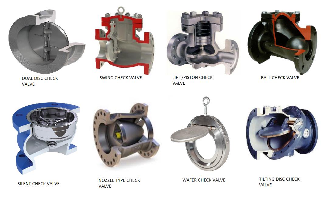
Check valves
Check valves are designed to prevent the reversal of flow in a piping system. The flowing material in the pipeline activates these valves. The pressure of the fluid passing through the system opens the valve, while any reversal of flow will close the valve. The closure is accomplished by the weight of the check mechanism, by back pressure, by a spring, or by a combination of these means. The general types of check valves are swing, tilting disk, piston, butterfly, and Stop.
Swing Check Valves
A swing check valve allows full, unobstructed flow and automatically closes as pressure decreases. These valves are fully closed when the flow reaches zero and prevent backflow. Turbulence and pressure drop within the valve is very low.
A swing check valve is usually recommended for use in systems employing gate valves because the figure Swing Check Valve Of the low-pressure drop across the valve. Swing check valves are available in either Y-pattern Or straight body design.
Tilting Disk Check Valves
The tilting disk check valve, illustrated in Figure, is similar to the swing check valve. Like the swing check, the tilting disk type keeps fluid resistance and turbulence low because of its straight-through design.
The disk lifts off of the seat to open the valve. The airfoil design of the disk allows it to “float” On the flow. Disk stops built into the body position the disk for optimum flow characteristics. A large body cavity helps minimize flow restriction. As flow decreases, the disk starts closing and seals before reverse flow occurs.
Lift Check Valves
A lift check valve is commonly used in piping systems in which globe valves are being used as a flow control valve. They have similar seating arrangements as globe valves. Lift check valves are suitable for installation in horizontal or vertical lines with upward flow. They are recommended for steam, air, gas, water, and vapor lines with high flow velocities. These valves are available in three body patterns horizontal, angle, and vertical.
Flow to lift check valves must always enter below the seat. As the flow enters, the disk or ball is raised within guides from the seat by the pressure of the upward flow. When the flow stops or reverses, the disk or ball is forced onto the valve’s seat by both the backflow and gravity.
Piston Check Valves
A piston check valve is essentially a lift check valve. It has a dashpot consisting of a piston and cylinder that provides a cushioning effect during operation. Because of the similarity in design to lift check valves, the flow characteristics through a piston check valve are essentially the same as through a lift check valve.
Piston check valves are used primarily in conjunction with globe and angle valves in piping systems experiencing very frequent changes in the flow direction. Valves of this type are used on water, steam, and air systems.
Butterfly Check Valves
Butterfly check valves have a seating arrangement similar to the seating arrangement of butterfly valves. Flow characteristics through these check valves are identical to the flow characteristics through butterfly valves. Consequently, butterfly check valves are quite frequently used in systems using butterfly valves. In addition, the construction of the butterfly check valve body is such that ample space is provided for unrestricted movement of the butterfly valve disk within the check valve body without the necessity of installing spacers.
The butterfly check valve design is based on a flexible sealing member against the bore of the valve body at an angle of 45. The disk’s short distance must move from full open to full closed inhibits the “slamming” action found in some other types of check valves. The Figure illustrates the internal assembly of the butterfly check valve.
Stop Check Valves
A stop check valve, illustrated in Figure, is a lift check valve and a globe valve. When closed, it has a stem that prevents the disk from coming off the seat and provides a tight seal (similar to a globe valve). When the stem is operated to the open position, the valve acts as a lift check. The stem is not connected to the disks and functions to close the valve tightly or limit the valve disk’s travel in the open direction.
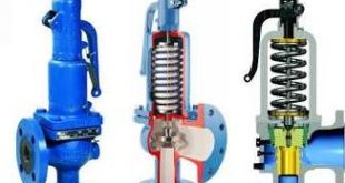
Relief & safety valve
Relief and safety valves prevent equipment damage by relieving accidental over-pressurization of fluid systems. The main difference between a relief valve and a safety valve is the extent of opening at the setpoint pressure. As illustrated in Figure, a relief valve gradually opens as the inlet pressure increases above the Setpoint. A relief valve opens only as necessary to relieve the over-pressure condition. Pressure safety valve theory and PSV valve mechanism.

As illustrated in Figure, a safety Valve rapidly pops fully open as soon as the pressure setting is reached. A safety valve will stay fully available until the pressure drops below a preset pressure. The reset pressure is lower than the actuating pressure setpoint. The difference between the actuating pressure setpoint and the pressure at which the safety valve resets is called blowdown. Blowdown is expressed as a percentage of the actuating pressure setpoint.
Solenoid Valve
- A solenoid valve is an electromagnetic valve for use with liquid or gas controlled by running or stopping an electrical current through a solenoid thus changing the state of the valve.
- A solenoid is a coil of wire that becomes magnetized when electricity is run through it.
- This type of valve is opened and closed by a plunger that is raised and lowered by the energizing and de-energizing of a solenoid.