 Boilersinfo Boiler and Mechanical Power Digital Library
There are 2 types of Refrigeration cycles:
1. Vapor Compression Cycle
2. Absorption Cycle
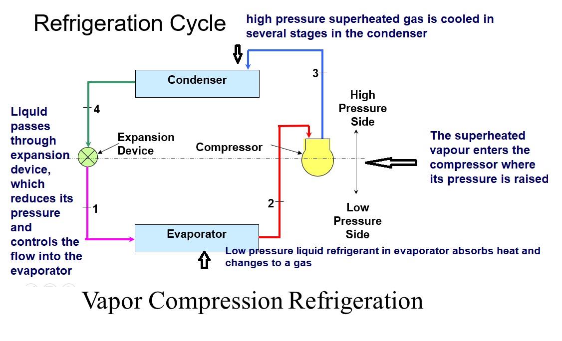
Vapor Compression Cycle
During the compression cycle, the refrigerant passes through four major components within the chiller. The evaporator, the compressor, the condenser, and a flow-metering device such as an expansion valve. The evaporator is the low-temperature (cooling) side of the system and the condenser is the high-temperature (heat-rejection) side of the system.
Key Components of Mechanical Compression Chillers:
Evaporator:
Chillers produce chilled water in the evaporator where the cold refrigerant flows over the evaporator tube bundle. The refrigerant evaporates (changes into vapor) as the heat is transferred from the water to the refrigerant. The chilled water is then pumped, via the chilled-water distribution system to the building’s air handling units.
The chilled water passes through coils in the air handler to remove heat from the air used to condition spaces throughout the building. The warm water (warmed by the heat transferred from the building ventilation air) returns to the evaporator and the cycle starts over.
Compressor:
Vaporized refrigerant leaves the evaporator and travels to the compressor where it is mechanically compressed and changed into a high-pressure, high-temperature vapor. Upon leaving the compressor, the refrigerant enters the condenser side of the chiller.
Condenser:
Inside the water-cooled condenser, the hot refrigerant flows around the tubes containing the condenser-loop water. The heat transfers to the water, causing the refrigerant to condense into liquid form. The condenser water is pumped from the condenser bundle to the cooling tower where heat is transferred from the water to the atmosphere. The liquid refrigerant then travels to the expansion valve.
Expansion valve:
The refrigerant flows into the evaporator through the expansion valve or metering device. This valve controls the rate of cooling. Once through the valve, the refrigerant expands to lower pressure and a much lower temperature. It flows around the evaporator tubes, absorbing the heat of the chilled water that’s been returned from the air handlers, completing the refrigeration cycle.
Type of Refrigerant
- Refrigerant determined by the required cooling temperature
- Chlorinated fluorocarbons (CFCs) or Freon’s: R-11, R-12, R-21, R-22, and R-502
- To select the appropriate refrigerant, their ODP (Ozone Depletion Potential) and GWP ( Global Warming Potential) need to be considered.
Selection
- Choice of the compressor, design of condenser, and evaporator determined by
- Refrigerant
- Required cooling
- Load
- Ease of maintenance
- Physical space requirements
- Availability of utilities (water, power)
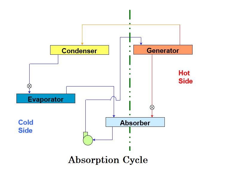
Absorption Cycle
The main components in the absorption cycle are:
- Solution Pump
- Condenser
- Evaporator
- Generator
- Absorber
Components of the absorption cycle
Solution Pump – A dilute lithium bromide solution is collected at the bottom of the absorber shell. From here, a hermetic solution pump moves the solution through a shell and tube heat exchanger for preheating.
Generator – After exiting the heat exchanger, the dilute solution moves into the upper shell. The solution surrounds a bundle of tubes that carries either steam or hot water. The steam or hot water transfers heat into the pool of dilute lithium bromide solution. The solution boils, sending refrigerant vapor upward into the condenser and leaving behind concentrated lithium bromide. The concentrated lithium bromide solution moves down to the heat exchanger, where it is cooled by the weak solution being pumped up to the generator.
Condenser – The refrigerant vapor migrates through mist eliminators to the condenser tube bundle. The refrigerant vapor condenses on the tubes. The heat is removed by the cooling water which moves through the inside of the tubes. As the refrigerant condenses, it collects in a trough at the bottom of the condenser.
Evaporator – The refrigerant liquid moves from the condenser in the upper shell down to the evaporator in the lower shell and is sprayed over the evaporator tube bundle. Due to the extreme vacuum of the lower shell [6 mm Hg (0.8 kPa) absolute pressure], the refrigerant liquid boils at approximately 39°F (3.9°C), creating the refrigerant effect. (This vacuum is created by hygroscopic action – the strong affinity lithium bromide has for water – in the Absorber directly below.)
Absorber – As the refrigerant vapor migrates to the absorber from the evaporator, the strong lithium bromide solution from the generator is sprayed over the top of the absorber tube bundle. The strong lithium bromide solution actually pulls the refrigerant vapor into the solution, creating an extreme vacuum in the evaporator. The absorption of the refrigerant vapor into the lithium bromide solution also generates heat which is removed by the cooling water. The now dilute lithium bromide solution collects in the bottom of the lower shell, where it flows down to the solution pump. The chilling cycle is now completed and the process begins once again.
Application of Chillers
- Chillers are used to cool the hot plastic in the plastic industry. It cools the plastic that is injected, blown extruded or stamped. They are also used to cool down the equipment used in the manufacturing process.
- In the printing industry, chillers are used to remove the heat generated by the printing rollers. They also help to cool the paper when it comes out of the ink-drying ovens.
- A sophisticated chiller is used in the high-powered electronics inside the machines like MRI and PET, used in the latest diagnostic tools.
- Chillers cool down the lasers and the source of power supply used to power them.