 Boilersinfo Boiler and Mechanical Power Digital Library
Improper operation of centrifugal pumps can result in damage to the pump and loss of function of the system that the pump is installed in. It is helpful to know what conditions can lead to pump damage to allow better understanding of pump operating procedures and how the procedures aid the operator in avoiding pump damage.
Many centrifugal pumps are designed in a manner that allows the pump to operate continuously for months or even years. These centrifugal pumps often rely on the liquid that they are pumping to provide cooling and lubrication to the pump bearings and other internal components of the pump. If flow through the pump is stopped while the pump is still operating, the pump will no longer be adequately cooled and the pump can quickly become damaged. Pump damage can also result from pumping a liquid whose temperature is close to saturated conditions.
Read Pump Books
Download Pumps Training Videos
Cavitation in centrifugal pump
The flow area at the eye of the pump impeller is usually smaller than either the flow area of the pump suction piping or the flow area through the impeller vanes. When the liquid being pumped enters the eye of a centrifugal pump, the decrease in flow area results in an increase in flow velocity accompanied by a decrease in pressure. The greater the pump flow rate, the greater the pressure drop between the pump suction and the eye of the impeller. If the pressure drop is large enough, or if the temperature is high enough, the pressure drop may be sufficient to cause the liquid to flash to vapor when the local pressure falls below the saturation pressure for the fluid being pumped. Any vapor bubbles formed by the pressure drop at the eye of the impeller are swept along the impeller vanes by the flow of the fluid. When the bubbles enter a region where local pressure is greater than saturation pressure farther out the impeller vane, the vapor bubbles abruptly collapse. This process of the formation and subsequent collapse of vapor bubbles in a pump is called cavitation. Cavitation in a centrifugal pump has a significant effect on pump performance. Cavitation can also be destructive to pumps internal components. When a pump cavitates, vapor bubbles form in the low pressure region directly behind the rotating impeller vanes. These vapor bubbles then move toward the oncoming impeller vane, where they collapse and cause a physical shock to the leading edge of the impeller vane. This physical shock creates small pits on the leading edge of the impeller vane. Each individual pit is microscopic in size, but the cumulative effect of millions of these pits formed over a period of hours or days can literally destroy a pump impeller. Cavitation can also cause excessive pump vibration, which could damage pump bearings, wearing rings, and seals.
Net Positive Suction Head To avoid cavitation in centrifugal pumps, the pressure of the fluid at all points within the pump must remain above saturation pressure. The quantity used to determine if the pressure of the liquid being pumped is adequate to avoid cavitation is the net positive suction head (NPSH). The net positive suction head available (NPSHA) is the difference between the pressure at the suction of the pump and the saturation pressure for the liquid being pumped. The net positive suction head required (NPSHR) is the minimum net positive suction head necessary to avoid cavitation. The condition that must exist to avoid cavitation is that the net positive suction head available must be greater than or equal to the net positive suction head required. This requirement can be stated mathematically as shown below.
NPSHA ≥ NPSHR
A formula for NPSHA can be stated as the following equation. NPSHA = Psuction – Psaturation
When a centrifugal pump is taking suction from a tank or other reservoir, the pressure at the suction of the pump is the sum of the absolute pressure at the surface of the liquid in the tank plus the pressure due to the elevation difference between the surface of liquid in the tank and the pump suction less the head losses due to friction in the suction line from the tank to the pump.
NPSHA = Pa + Pst – hf – Psat
NPSHA = net positive suction head available
Pa = absolute pressure on the surface of the liquid
Pst = pressure due to elevation between liquid surface and pump suction
hf = head losses in the pump suction piping
Psat = saturation pressure of the liquid being pumped
Preventing Cavitation
If a centrifugal pump is cavitating, several changes in the system design or operation may be necessary to increase the NPSHA above the NPSHR and stop the cavitation. One method for increasing the NPSHA is to increase the pressure at the suction of the pump. For example, if a pump is taking suction from an enclosed tank, either raising the level of the liquid in the tank or increasing the pressure in the space above the liquid increases suction pressure. It is also possible to increase the NPSHA by decreasing the temperature of the liquid being pumped. Decreasing the temperature of the liquid decreases the saturation pressure, causing NPSHA to increase.
Centrifugal Pump Curves
For a given centrifugal pump operating at a constant speed, the flow rate through the pump is dependent upon the differential pressure or head developed by the pump. The lower the pump head, the higher the flow rate. A vendor manual for a specific pump usually contains a curve of pump flow rate versus pump head called a pump characteristic curve. After a pump is installed in a system, it is usually tested to ensure that the flow rate and head of the pump are within the required specifications. A typical centrifugal pump characteristic curve is this.
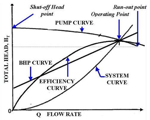
There are several terms associated with the pump characteristic curve that must be defined. Shutoff head is the maximum head that can be developed by a centrifugal pump operating at a set speed. Pump runout is the maximum flow that can be developed by a centrifugal pump without damaging the pump. Centrifugal pumps must be designed and operated to be protected from the conditions of pump runout or operating at shutoff head. Additional information may be found in the handbook on Thermodynamics, Heat Transfer, and Fluid Flow.
Centrifugal Pump Protections
A centrifugal pump is dead-headed when it is operated with no flow through it, for example, with a closed discharge valve or against a seated check valve. If the discharge valve is closed and there is no other flow path available to the pump, the impeller will churn the same volume of water as it rotates in the pump casing. This will increase the temperature of the liquid (due to friction) in the pump casing to the point that it will flash to vapor. The vapor can interrupt the cooling flow to the pump’s packing and bearings, causing excessive wear and heat. If the pump is run in this condition for a significant amount of time, it will become damaged. When a centrifugal pump is installed in a system such that it may be subjected to periodic shutoff head conditions, it is necessary to provide some means of pump protection. One method for protecting the pump from running dead-headed is to provide a recirculation line from the pump discharge line upstream of the discharge valve, back to the pump’s supply source. The recirculation line should be sized to allow enough flow through the pump to prevent overheating and damage to the pump. Protection may also be accomplished by use of an automatic flow control device. Centrifugal pumps must also be protected from runout. Runout can lead to cavitation and can also cause overheating of the pump’s motor due to excessive currents. One method for ensuring that there is always adequate flow resistance at the pump discharge to prevent excessive flow through the pump is to place an orifice or a throttle valve immediately downstream of the pump discharge. Properly designed piping systems are very important to protect from runout.