 Boilersinfo Boiler and Mechanical Power Digital Library
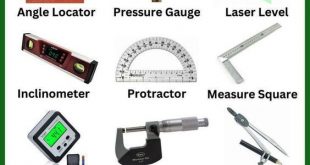
Some precision measuring tools are more accurate than others, but all can be read at least to the nearest 0.001 inches or 0.02 millimeters. There are four broad categories of precision measuring tools:
• outside measuring tools, for measuring the diameter of a shaft or the thickness of a block;
• inside measuring tools, for measuring the diameter of a bore or the width of a slot;
• depth gauges, for measuring the depth of a hole or recess;
• height gauges, for measuring the height of a feature above a flat surface.
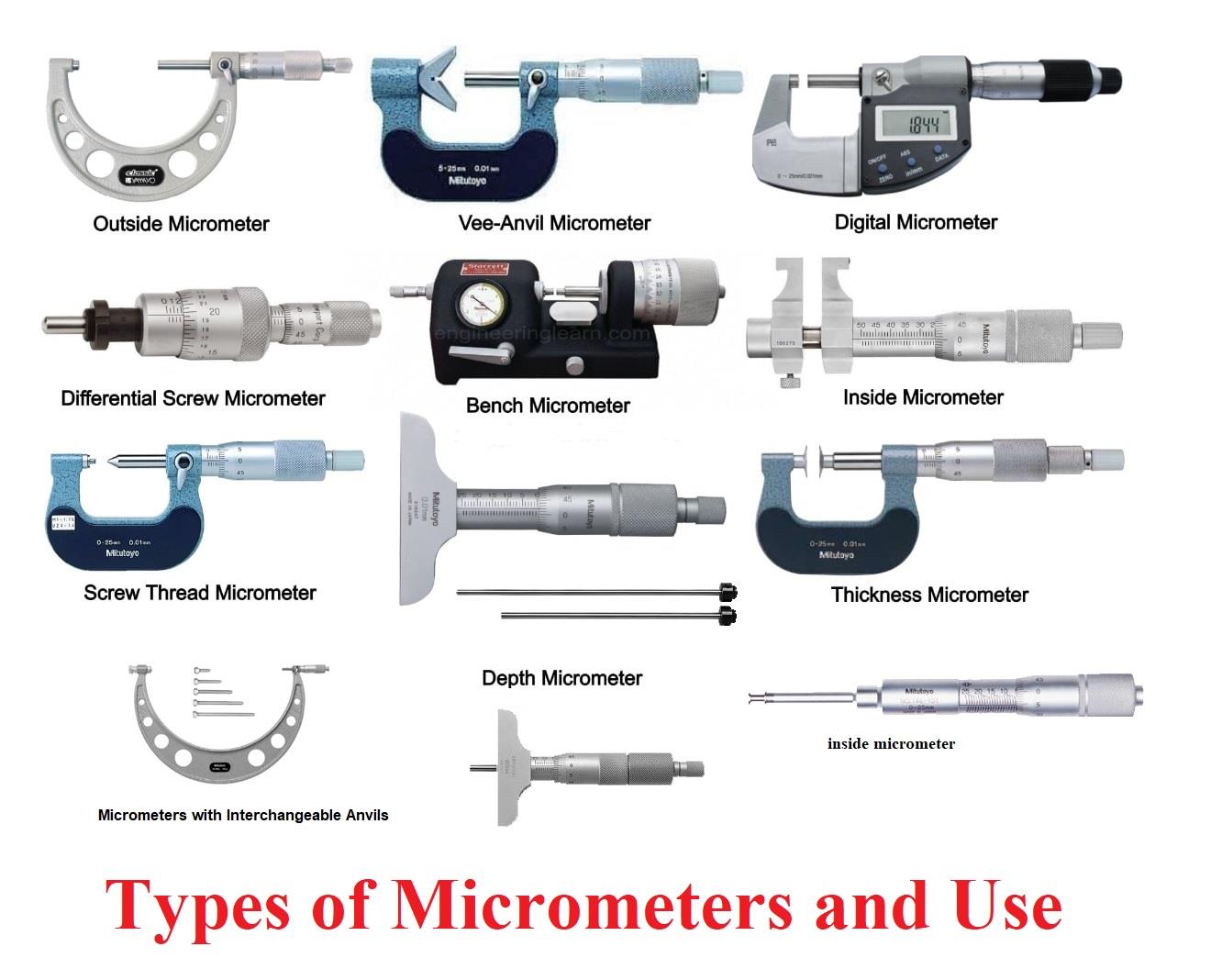
Outside Micrometers
An outside micrometer caliper, better known as an outside micrometer, is usually the first precision measuring tool an apprentice buys. No other measuring tool is as consistently accurate and easy to read, and a good millwright ensures that all final measurements are made with a micrometer that is properly adjusted and well cared for.
Micrometer Construction
Although a micrometer is a precision instrument, it is based on a very simple principle. Essentially, it uses a screw thread to convert circular motion into linear motion. Inside the micrometer is an accurately ground steel screw that turns into an equally accurate nut. When the screw is rotated it moves a precise distance in and out of the nut.
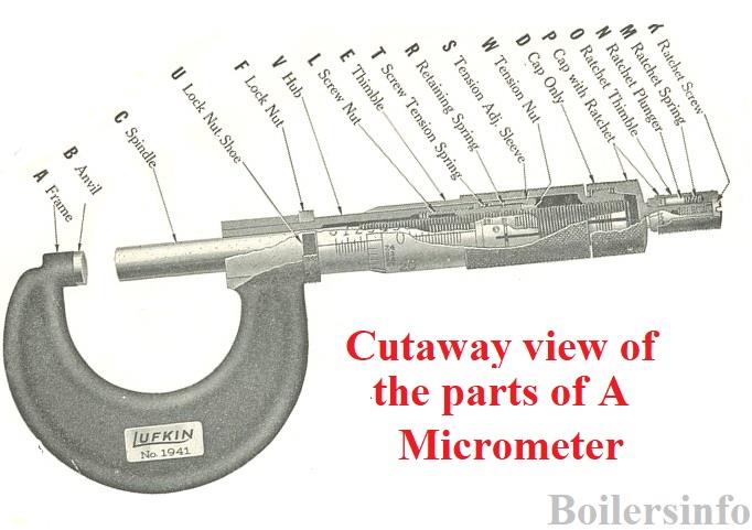
Work is checked for size between the two measuring faces of the micrometer. The measuring faces consist of the anvil and the spindle. The spindle is part of the screw and moves to accommodate different sizes of work between the measuring faces. The anvil is attached to a rigid frame and does not move. The contact surfaces are usually made of carbide to resist wear.
The reading is taken by noting the position of the thimble against the sleeve. This procedure is discussed in detail in the objective of measuring components using outside and inside measuring tools.
A ratchet or friction thimble at the end of the screw allows the user to close the micrometer with consistent pressure. The locknut or lever is used to set the micrometer firmly to a particular size.
Micrometer Sizes
Each imperial micrometer has a range of only 1 inch, meaning that it will measure from 0 to 1 inch, or from 1 to 2 inches, or from 2 to 3 inches, and so on. Micrometers are sized according to the largest workpiece they can measure. For example, a 1-inch micrometer measures from 0 to 1 inch. A 2-inch micrometer measures from 1 inch to 2 inches. A set of micrometers may cover a range of size up to 24 inches.
Micrometers with Interchangeable Anvils
These micrometers are popular in maintenance shops and applications requiring a versatile micrometer. Each micrometer is equipped with a series of easily interchangeable anvils, thus providing the full range of steps of 1 inch or 25 millimeters with a single micrometer. When an anvil is changed, the size should be checked with the standards supplied. Suitable wrenches are furnished to make any necessary adjustments.
Metric Micrometers
A standard metric micrometer has a range of 25 mm and can read to an accuracy of 0.01 mm. Like imperial micrometers, they are sized according to the largest workpiece they can measure.
Vernier Micrometers
A standard inch micrometer can only measure to 0.001 inches. This is the discrimination of the instrument or the smallest readable division. Any attempt to read a standard micrometer more finely than that is a guess. A vernier micrometer offers greater precision because it subdivides 0.001″ by 10 parts. Therefore, the finest reading off a vernier micrometer is 0.0001 inches. Even though a vernier micrometer can be read to 0.0001 inches, it takes a great amount of skill to measure this level of accuracy.
Combination Inch-Metric Micrometer
The combination inch-metric micrometer can measure both imperial and metric sizes. Such micrometers have become less common since electronic digital micrometers were introduced. Some combination micrometers have imperial graduations on the sleeve and display
metric units in the readout. Others are reversed, with metric graduations on the sleeve and imperial units displayed in the readout. Still, others have both imperial and metric graduations on the sleeve.
Electronic Digital Micrometer
An electronic digital micrometer determines a size electronically and then displays it on an easy-to-read numeric readout. These micrometers have a number of features that make them increasingly popular.
• The large numeric readout is easy to see.
• There is less chance of misreading a size than with a mechanical micrometer.
• The dimensions can be easily switched from imperial to metric.
• The zero point can be set anywhere within the micrometer’s range, allowing comparison measurement.
Using Outside Micrometers
An outside micrometer is an accurate measuring instrument. The ability to use a micrometer well is basic to the millwright trade. There are five steps to follow when using a micrometer.
1. Clean the measuring faces.
2. Check the micrometer for zero setting.
3. Align the micrometer correctly with the workpiece.
4. Close the micrometer on the workpiece with the correct degree of pressure.
5. Read the micrometer
Applying the Proper Measuring Pressure
A micrometer screw exerts great pressure when tightened. Too much pressure will distort the frame of the micrometer. If the workpiece is delicate it will also distort. Even a very small change in the pressure used to close a micrometer can change the reading by more than 0.001 inches. The trick to accurate measurement is to apply the same amount of pressure every time and to make sure the pressure is small enough to prevent distortion. The ability to do this is called feel and must be learned through practice. The ratchet method is more consistent than using feel. The ratchet is set to release at the same pressure each time. No matter how many times a measurement is taken, the measurement will always be the same. Sometimes it is convenient to hold a small workpiece in one hand while operating the micrometer with the other. In this case, it is impossible to reach the ratchet, and you must rely on feel to close the micrometer. Many millwrights lightly tum the smooth part of the thimble until their fingers just slip over the surface. This technique is fairly consistent as long as the same person uses the micrometer. A problem arises when different people use the micrometer because each person has a different feel.
Cleaning the Measuring Faces
A micrometer cannot measure to 0.001 inches (0.01 mm) if there is dirt or grit on the measuring faces. Before taking any measurement, clean each measuring face with your finger or the palm of your hand. If an especially fine measurement is required, gently close the micrometer on a piece of paper and pull the paper through.
Checking for Zero Setting
When closing is sure to use the ratchet stop. To check that a micrometer is properly calibrated, close it on itself with the same pressure
you would use for taking a measurement. If the micrometer reads zero, it is still calibrated. If not, it will have to be adjusted. Any micrometer larger than 1 inch or 25 mm comes with a reference standard. Using the ratchet stop, close the micrometer on this standard and see if it reads zero.
Get Free ebook [pdf] Measuring and Marking Metals
Reading an Imperial Vernier Micrometer
It is only possible to measure to 0.001 inches with a standard inch micrometer. Any attempt to read between the thimble graduations would be guessing. A vernier micrometer uses a vernier scale to allow readings to 0.0001 inches. To read a vernier micrometer, follow the three steps for reading a standard inch micrometer, then add one extra step:
l. Look to see where the front edge of the thimble lines up with the index line. On the main scale in Figure, the front edge crosses the index line just after the 0.525-inch mark.
2. Look to see where the index line on the sleeve lines up with the thimble. On the main scale in Figure, the index line lines up closest to the 0.003-inch line on the thimble. When the index line passes between two lines on the thimble, as it does here, pick the line below the index line. Do not try to guess parts of thousandths of an inch.
3. Add the reading from the main scale (0.525 inches) to the reading from the thimble (0.003 inches). In Figure, the initial reading is 0.528 inches.
4. Now, tilt the micrometer over and read the vernier scale. Look to see which graduation on the vernier scale lines up exactly with any line on the thimble. In Figure the second line on the vernier scale lines up exactly, representing 0.0002 inches. Add this to the reading from step 3. In Figure the final reading is 0.5282 inch (0.528 inch+ 0.0002 inch = 0.5282 inch).
Reading a Metric Micrometer
The pitch of a metric micrometer screw is 0.5 mm. Every time the screw is turned one complete revolution the spindle moves exactly half a millimeter. It follows that if the screw is turned one-fiftieth of a revolution, the spindle moves 0.01 mm. The graduations on the main scale are spaced every 0.5 mm, corresponding with the pitch of the screw. Graduations above the index line are whole millimeters, and the graduations below the index line are half millimeters. There are 50 graduations around the circumference of the thimble, each representing 0.01 mm.
Use the same three steps for reading a metric micrometer as you would for reading an inch micrometer.
1. Look to see where the front edge of the thimble lines up with the main scale. In Figure, it crosses just after the 16-mm mark.
2. Look to see where the index line on the sleeve lines up with the thimble. In Figure, it lines up with the 0.05-mm line.
3. Add the reading from the main scale (16 mm) to the reading from the thimble (0.05 mm). In Figure the final reading is 16.05 mm (16 mm + 0.05 mm = 16.05 mm).
Inside Micrometers
Inside measurement is more difficult than outside measurement because space is limited and it can be difficult to align the measuring tool with the true diameter.
There are two techniques for measuring inside a bore or recess.
• Use an inside micrometer to take a direct reading.
• Set a telescoping gauge or small-bore gauge to the size of the bore or recess, and then measure the gauge with an outside micrometer.
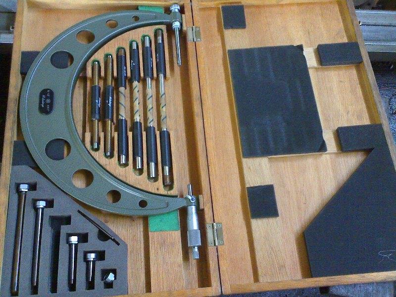
The inside micrometer is the most common direct reading inside measuring tool. It comes in a set containing a micrometer barrel and a number of interchangeable measuring rods. Metric inside micrometers have either a 13 mm or 25mm movement. The measuring rods are sized in increments of25 mm. Insets with a 13 mm movement, there is a 12.5 mm spacer to be used with the measuring rods. These measuring rods extend the range of the micrometer, but they are also a source of error if installed carelessly. There is a handle to hold the micrometer when it is used deep inside a bore.
Using an Inside Micrometer
The trick to measuring a bore accurately is to align the measuring tool two ways:
• exactly across the diameter of the bore and
• exactly at right angles to the axis of the bore.
Other than that, inside measuring tools are used the same way as outside ones. An inside micrometer can be used deep inside a bore, and it can be used on a wide range of bore sizes because it has interchangeable measuring rods. One disadvantage is that an inside micrometer must be aligned both across the diameter of a bore and at right angles to the axis of the bore. You have two chances to get it wrong, instead of
just one.
To measure a bore with an internal micrometer follow these steps.
1. Choose a measuring rod of the correct length and install it on the body of the micrometer. Make sure the mating surfaces are absolutely clean.
2. Check the calibration of the micrometer against a master ring gauge or an accurate outside micrometer.
3. If the measurement is to be taken deep inside the bore, install the handle.
4. Place the micrometer in the bore. Hold the fixed anvil in place against one side of the bore. Open the micrometer to bring the movable anvil into contact with the opposite side. Determine the correct alignment by rocking the micrometer in and out and from side to side. The micrometer should just pull through the bore with a slight amount of drag.
5. The inside micrometer has no spindle lock, so the reading should be taken while the micrometer is still in the bore. This is not always possible., Therefore, to prevent the spindle from moving, the adjusting nut should be slightly tighter than normal.
6. Read the micrometer.
Depth Micrometer
The micrometer depth gauge, more commonly known as a depth micrometer, has a micrometer head attached to a flat base. Each set contains a number of interchangeable measuring rods, each 1 inch (25 mm for metric) longer than the next. You must clean and install these measuring rods carefully or accuracy will suffer. It is important to remember that the graduations on the sleeve of a depth micrometer are numbered in the opposite direction to a standard micrometer.
Using a Depth Micrometer
To use a depth micrometer follow these steps.
1. Install a measuring rod of the correct length. Make sure the mating surfaces are absolutely clean.
2. Check for proper calibration (see Calibrating the Measuring Rods of a Depth Micrometer).
3. Remove dirt or grit from the base of the micrometer and the surface of the work.
4. Place the base of the micrometer firmly on the upper surface of the work and tum the micrometer screw until the end of the measuring rod lightly contacts the lower surface. Use the ratchet to gauge the proper pressure.
5. A depth micrometer will not tighten on the workpiece. You must hold the base of the micrometer firmly in contact with the surface of the work or it will rise.
This micrometer has a 0 to 1-inch measuring rod installed. The main scale numbering on the sleeve of a depth micrometer runs opposite to
that on most other micrometers. The distance to be measured is the amount of the main scale on the sleeve covered by the thimble.
Calibrating the Outside Micrometer Mechanism
When the micrometer is closed, either on itself or on a standard, the zero mark on the thimble must line up with the index line on the sleeve. If they do not line up, clean the anvil, spindle, and standard and inspect the measuring faces for any damage. If the two lines still do not coincide after cleaning, rotate the sleeve until they do line up.